Hot Articles
Popular Tags
What causes a dosing pump controller to lose calibration?
What Causes a Dosing Pump Controller to Lose Calibration?
When a dosing pump controller loses calibration, the visible symptom is usually simple: the process is receiving more or less chemical than expected. The underlying cause is rarely as simple. A controller may be issuing the correct command while the pump delivers the wrong volume. Or the pump may be mechanically sound, but the controller is being misled by a drifting sensor, an unstable input signal, or a parameter that was changed during a previous service visit.
In water treatment, surface finishing, food processing, chemical manufacturing, and utility systems, even a small dosing error can become a larger operating problem. Residual levels move outside their normal band, pH control hunts, product quality becomes inconsistent, or chemical consumption rises without an obvious reason. The maintenance challenge is to determine whether this is a true calibration loss in the dosing pump controller, a flow-side delivery problem, or a process measurement problem presenting itself as a dosing fault.
The practical rule is this: do not recalibrate immediately just because the process value looks wrong. First establish which signal in the loop can be trusted. A rushed recalibration can hide a worn check valve, a blocked injection point, or a faulty flow transmitter for long enough to create a repeat failure.
Calibration loss is often a chain of small errors
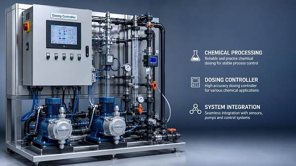
A dosing system is a chain: controller output, motor or actuator response, pump stroke, suction conditions, chemical properties, pipework, injection conditions, and sometimes a feedback instrument. Calibration can appear to drift when any part of that chain changes. This matters because maintenance teams often focus on the controller display while the actual fault is downstream.
For example, a controller may command a diaphragm metering pump to operate at a fixed stroke frequency. If the suction line develops an air leak, the pump can continue cycling normally while each stroke moves less liquid. The controller has not technically lost calibration, yet the delivered chemical volume no longer matches the assumed output. The same pattern occurs when fluid viscosity rises, a foot valve sticks, crystallization forms around the injection quill, or a pressure change alters pump performance.
This is why a good fault investigation separates command accuracy from delivery accuracy. A stable 4–20 mA command signal does not prove a stable dosing rate, and a stable pump speed indication does not prove that the process is receiving the intended chemical mass.
Sensor drift and bad feedback signals
Where dosing is controlled by flow, pH, conductivity, oxidation-reduction potential, residual chemical measurement, tank level, or another process variable, sensor condition is one of the first areas to inspect. Sensors do not always fail abruptly. They can drift gradually due to coating, aging, electrolyte depletion, fouling, temperature effects, damaged cables, or poor installation position.
A pH electrode installed in a dirty sample line, for instance, may respond slowly rather than report an obviously impossible value. The controller sees a delayed or biased signal and continues increasing the chemical dose. Eventually the true process condition overshoots, but the displayed feedback may still look plausible. In this situation, recalibrating the dosing pump controller will not solve the real problem.
Confirm the measurement independently before changing controller values. Use the site-approved reference method, a recently verified portable instrument, or a laboratory sample where appropriate. Compare the field measurement, transmitter output, controller display, and raw input signal. If these do not agree, trace the discrepancy before touching the dosing setpoint or pump calibration factor.
Feedback instruments should also be checked for configuration mismatches. Common issues include an incorrect engineering range, a changed transmitter scaling value, the wrong temperature compensation setting, or a controller input configured for voltage when the field device provides current. These errors are especially likely after transmitter replacement, panel modification, firmware updates, or control-system migration.
Electrical interference, grounding, and unstable analogue signals
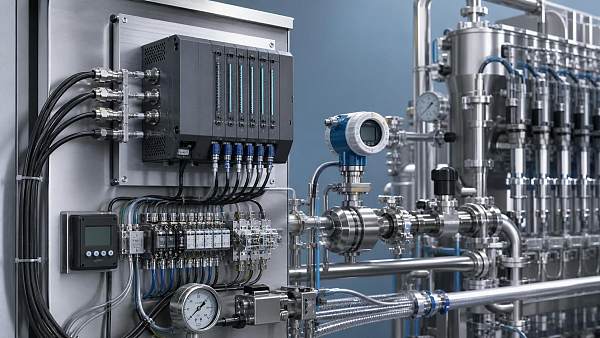
A dosing pump controller can appear to lose calibration when its input or output signal is electrically unstable. Variable-frequency drives, large motors, contactors, solenoid valves, welding equipment, and poorly segregated power cables can introduce noise into low-level analogue circuits. The effect may be intermittent: dosage changes during a mixer start, a transfer pump cycle, or a nearby motor acceleration event.
The 4–20 mA loop is generally robust, but it is not immune to poor terminations, damaged shielding, water ingress in junction boxes, corroded terminals, or an incorrect grounding arrangement. A loose common connection may not create an immediate alarm. Instead, the controller input can fluctuate just enough to produce unstable speed commands or misleading flow readings.
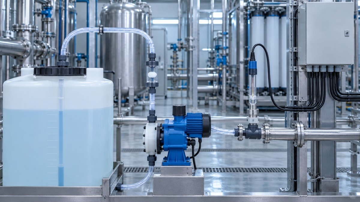
During troubleshooting, do not rely only on the controller screen. Measure the actual signal at the controller terminals and, where relevant, at the transmitter or pump drive. Check whether the reading is steady under normal operation and while adjacent equipment starts and stops. Inspect cable routing. Signal cables running alongside unshielded motor conductors for a long distance deserve attention, particularly in older skid installations where later modifications were made without revisiting the original wiring layout.
Power quality can also matter. Low supply voltage, voltage dips, weak backup power, or repeated restart events may corrupt retained settings in some equipment or cause a controller to restart with fallback parameters. If calibration changes repeatedly after outages, compare stored settings before and after a controlled power cycle and review event logs if the controller provides them.
Incorrect parameters after maintenance or replacement
Parameter mistakes are among the most avoidable causes of apparent calibration loss. They are also common because a dosing loop may contain several places where scaling is applied: the transmitter, PLC or standalone controller, pump drive, local pump controller, and supervisory system. A technician may adjust one value without knowing another layer already applies a multiplier, ratio, or limit.
Typical errors include entering the wrong pump capacity, selecting the wrong control mode, changing pulse scaling, reversing a direct-acting or reverse-acting response, or restoring a backup from a different pump duty. A pump replacement creates particular risk. Two pumps may have similar names or physical dimensions but different displacement per stroke, maximum stroke frequency, gearbox ratios, or motor-control requirements.
A useful discipline is to preserve a configuration record before work begins. Record the controller setpoint, input and output ranges, calibration constants, alarms, stroke length, maximum speed, dosing ratio, and any flow-paced calculation. Take clear photographs of local settings where permitted. After commissioning, perform a controlled comparison between commanded output and measured delivery rather than assuming that copied parameters are correct.
Be cautious with “auto-calibration” functions. They can be useful when the system has reliable feedback and stable operating conditions. They are not a substitute for verifying suction conditions, chemical concentration, backpressure, and pump condition. An automatic routine can accurately learn the behavior of a pump that is already compromised by air entrainment or a partially blocked line.
Mechanical wear changes the pump’s real output
The controller may retain its calibration perfectly while the pump no longer delivers its former volume per stroke. Diaphragms age, valve balls and seats wear, seals leak, plungers score, gearboxes develop backlash, and flexible tubing in peristaltic pumps loses recovery. These changes are often gradual, which is exactly why they are mistaken for controller drift.
Check valves deserve close attention in metering-pump service. Debris, chemical crystals, incompatible elastomers, or worn sealing surfaces can prevent the valve from seating consistently. The result may be reduced capacity, poor repeatability, or dose variation that changes with discharge pressure. A pump can pass a quick no-load test yet fail to achieve the same output when connected to the operating injection pressure.
For that reason, a calibration test should resemble actual duty as closely as practical. If the pump normally operates against a pressurized process line, testing into an open container may provide only partial evidence. Consider the effect of backpressure, pulsation dampeners, relief valves, injection fittings, and changing tank levels. The controller cannot compensate for hydraulic behavior it does not measure.
Chemical changes are another overlooked factor. A batch with higher viscosity, a colder storage temperature, suspended solids, or gas release can alter volumetric performance. Where chemical is diluted on site, confirm that the assumed concentration is still correct. A volumetric delivery check may pass while the actual active-chemical dose is wrong because the feed solution itself has changed.
Poor suction conditions and injection-side restrictions
Many “calibration” complaints start at the suction side. Air leaks may be too small to show as liquid leakage. A cracked suction hose, loose fitting, hardened seal, clogged strainer, collapsed flexible line, or low chemical level can reduce pump fill volume. In diaphragm systems, visible bubbles in a clear suction line are useful evidence, but their absence does not fully rule out air ingress.
On the discharge side, blocked injection quills, scaled non-return valves, excessive backpressure, or an incorrectly set pressure relief device can distort output. Some installations develop deposits exactly where the chemical meets process water. This is common with incompatible chemical combinations or with conditions that encourage precipitation. The controller may increase output in response to poor feedback, making the buildup and the process instability worse.
Before recalibration, inspect the physical route from chemical tank to injection point. Confirm that isolation valves are fully open, strainers are clean, venting arrangements are correct, and the injection location has not changed. A modification to pipework or a new process pump can alter backpressure enough to invalidate an old field calibration.
A practical fault-isolation sequence
The fastest route to a reliable diagnosis is usually a controlled sequence rather than repeated adjustments. Start by placing the process in a safe operating condition under site procedures. Verify the chemical identity, concentration, tank level, and current duty. Review whether there has been recent maintenance, a power event, a chemical supplier change, controller replacement, or pipework modification.
Then compare four things: the controller’s requested output, the electrical command reaching the pump or drive, the pump’s actual mechanical response, and the measured liquid delivery. If a flow meter is installed, do not assume it is the reference without checking its condition and range. A timed volumetric test, performed safely and with suitable collection equipment, is often a valuable cross-check for low-to-moderate flow dosing duties.
If command and pump movement agree but measured volume does not, inspect the pump head, valves, suction path, and discharge restriction. If measured volume agrees but the process result does not, investigate chemical concentration, injection location, mixing, residence time, and the feedback instrument. If the controller command itself is unstable, focus on inputs, wiring, configuration, electrical noise, and control logic.
This distinction prevents a familiar maintenance trap: recalibrating the controller until the process looks acceptable, then discovering weeks later that the underlying hardware or measurement fault has become worse.
Preventing repeat calibration problems
Calibration reliability is less about a single annual check than about controlling the conditions around the dosing loop. Maintain configuration backups, but label them clearly by pump duty and revision. Lock or password-protect critical parameters where the equipment supports it. Keep replacement wetted parts and cable components compatible with the actual chemical and environment, not merely with the pump model.
For critical installations, maintenance records should connect controller settings to the physical system: pump head type, tubing or diaphragm material, valve arrangement, chemical concentration, normal discharge pressure, and verification method. This level of traceability is particularly valuable in large industrial estates and multi-site operations, where component substitutions and supply-chain changes can quietly affect established settings.
Within intelligent flow metering and control systems, the most dependable practice is to treat the controller, pump, sensors, and fluid path as one verified loop. That systems view is more useful than blaming the electronics by default. A dosing pump controller usually does not “forget” calibration without a reason; the task is to find whether the reason lies in its settings, its signals, the pump’s condition, or the process it is trying to control.
Recommended News
 Oct 10, 2026How Flow Control Automation Improves Dosing Accuracy in Chemical ProcessingFlow control automation improves chemical dosing accuracy with real-time feedback, smarter control logic, safer operation, and reliable lifecycle performance.● Elena Hydro
 Oct 18, 2026What causes a dosing pump controller to lose calibration?Dosing pump controller calibration issues explained: identify sensor drift, wiring faults, parameter errors, pump wear, and flow restrictions with practical troubleshooting steps.● Elena Hydro
 Oct 17, 2026How a chemical dosing pump controller prevents overfeedingChemical dosing pump controller safeguards prevent overfeeding with flow pacing, feedback, interlocks, and output limits. Learn smarter, safer dosing control.● Elena Hydro
 Sep 14, 2026How Food Processors Can Evaluate Dosing Controller Manufacturers for Hygienic AccuracyDosing controller manufacturer food processing guide: evaluate hygienic design, delivered-dose accuracy, CIP cleanability, allergen controls, alarms, and validation evidence.● Elena Hydro
 Aug 08, 2026How to Evaluate a Dosing Controller Manufacturer for Chemical Processing ProjectsDosing controller manufacturer chemical processing buyers trust should deliver accuracy, safe integration, and reliable support. Learn how to compare suppliers and reduce project risk.● Elena Hydro
 Jul 30, 2026Batch Controller Cost Breakdown: What Affects Price and Total Ownership?Batch controller cost depends on more than unit price. Discover what drives total ownership, from meter compatibility and integration to compliance, maintenance, and downtime risk.● Elena Hydro
 Jul 05, 2026Proportional Valve Hysteresis in Europe: Test Methods, Compliance, and Selection FactorsProportional valve hysteresis Europe explained: compare test methods, compliance expectations, and selection factors to choose stable, efficient valves with confidence.● Elena Hydro
 Jul 03, 2026Liquid Dosing System Manufacturer Checklist: 7 Questions Before You Request a QuoteLiquid dosing system manufacturer checklist: discover 7 key questions to compare accuracy, compliance, support, and total cost before requesting a quote.● Elena Hydro
 Jul 02, 2026Mass Flow Controllers Supplier Checklist: How to Compare Accuracy, Lead Time, and SupportMass Flow Controllers supplier checklist: compare accuracy specs, real lead times, and after-sales support to reduce downtime, control total cost, and choose with confidence.● Elena Hydro
 Jun 26, 2026Technical Comparison of Coriolis vs Magnetic Flow Meters for Accurate DosingTechnical Comparison of Coriolis vs Magnetic Flow Meters for accurate dosing—learn which option delivers better precision, reliability, and lower lifecycle risk.● Elena Hydro
 Jun 18, 2026Liquid Dosing System Factory Selection: Key Accuracy, Flow Rate, and Control FactorsLiquid dosing system factory selection starts with accuracy, flow stability, and control performance. Learn how to compare suppliers for reliable output, lower waste, and long-term process confidence.● Elena Hydro
 Jun 08, 2026Liquid Dosing System Factory Selection Guide: Accuracy, Flow Rate, and Control OptionsLiquid dosing system factory selection starts with proven accuracy, stable flow rate, and smart control options. Compare key criteria to reduce risk and choose a reliable supplier.● Elena Hydro
 May 23, 2026Flow Control issues that quietly raise energy and maintenance costsFlow Control issues can silently increase energy use and maintenance costs. Learn the warning signs, root causes, and smart evaluation steps to improve reliability and reduce lifecycle risk.● Elena Hydro
 May 22, 2026Flow control mistakes that quietly raise energy useFlow Control mistakes can quietly increase energy use, raise wear, and destabilize processes. Learn the hidden causes, key risks, and smarter ways to improve industrial efficiency.● Elena Hydro
 May 21, 2026Flow Control problems often start with one wrong assumptionFlow Control problems often start with one wrong assumption. Discover how to spot hidden risks, improve reliability, and make smarter industrial design and sourcing decisions.● Elena Hydro
 May 20, 2026Flow Control mistakes that lead to unstable outputFlow Control mistakes can trigger unstable output, higher downtime, and compliance risk. Learn the key errors, warning signs, and smarter selection strategies to improve reliability.● Elena Hydro
 May 19, 2026How to judge flow control stability before buyingFlow Control stability starts with real-world testing. Learn how to compare pressure response, repeatability, and lifecycle performance before buying with confidence.● Elena Hydro
 May 18, 2026Common flow control mistakes that raise system riskFlow Control mistakes in sizing, installation, and maintenance can quietly raise downtime and safety risk. Learn the hidden errors that impact reliability and sourcing decisions.● Elena Hydro
 May 17, 2026What to Check Before Upgrading a Flow Control SystemFlow Control upgrade guide: learn what to check before changing a system, from media compatibility and pressure limits to integration, compliance, and long-term reliability.● Elena Hydro
 May 16, 2026Flow Control issues that quietly increase operating costsFlow Control issues often raise operating costs long before failure occurs. Discover how pressure drift, leakage, oversizing, and poor response silently drain energy, uptime, and profit.● Elena Hydro
 May 15, 2026Flow Control Settings That Look Stable but Waste OutputFlow Control settings may look stable yet quietly cut throughput and raise energy use. Learn how to spot hidden output loss, judge settings by scenario, and improve capacity without sacrificing reliability.● Elena Hydro
 May 14, 2026Flow Control Problems That Raise Energy Use Without WarningFlow Control problems can quietly drive up energy costs, reduce reliability, and strain equipment. Discover the hidden warning signs, key system risks, and practical fixes before losses grow.● Elena Hydro
 May 13, 2026Flow Control problems that quietly raise energy costsFlow Control issues can quietly drive up energy costs through pressure swings, oversizing, drift, and poor tuning. Learn where waste hides and how to cut it before reliability and budgets suffer.● Elena Hydro
 May 12, 2026Flow Control Problems That Look Small but Hurt OutputFlow Control issues that seem minor can quietly cut output, raise scrap, and increase downtime. Learn the warning signs and practical fixes that restore stability fast.● Elena Hydro