Hot Articles
Popular Tags
How a chemical dosing pump controller prevents overfeeding
Overfeeding is rarely caused by a dosing pump “running too well.” More often, the pump is receiving the wrong command, reacting to a misleading signal, or continuing to dose after the process has already changed. A chemical dosing pump controller prevents this by turning chemical injection from a fixed mechanical action into a controlled response: it limits output, adjusts dosing against a relevant process input, and stops or alarms when conditions no longer make sense.
This matters wherever the chemical demand changes with water flow, production rate, pH, conductivity, oxidation-reduction potential, tank level, or batch stage. In these applications, setting a pump to one manual speed may work briefly, then become excessive when demand falls. The result can be chemical waste, unstable treatment results, corrosion, scaling, off-spec product, or unnecessary safety exposure.
Overfeeding usually begins with a mismatch between dose and demand
A metering pump delivers a repeatable amount per stroke or per unit of running time. That does not mean the required dose is constant. If incoming flow drops but the pump remains at the same speed, the chemical concentration rises. If a pH probe is dirty and reports a value that is too high, an acid or caustic control loop may keep dosing in the wrong direction. If a transfer pump stops but the dosing pump continues, chemical can accumulate in a line or small vessel.
The controller’s role is to recognize these changing conditions and keep the pump output inside a defined operating range. It may do this through a simple run/stop interlock, a flow-proportional signal, a feedback loop, or a combination of these methods. The best approach depends on how quickly the process changes and how reliable the measurement is.
It is useful to separate accurate pump calibration from accurate process dosing. Calibration confirms how much chemical the pump can deliver. Control confirms whether that amount is appropriate at that moment. A correctly calibrated pump can still overfeed if its controller has no valid reason to reduce or stop the dose.
How a chemical dosing pump controller creates practical safeguards
A well-configured controller does not rely on a single protection. It uses several layers, because one sensor, one setpoint, or one pump status signal can fail or become misleading.
It applies a maximum output limit
The first protection is a ceiling on pump speed, stroke rate, or dosing frequency. Even if a control signal requests full output, the controller can be configured so the pump cannot exceed the maximum chemical feed rate that the process can safely accept.
This limit should be based on the chemical concentration, pump calibration, injection point, tank or pipe volume, and the consequences of a high dose. It should not simply be set at the pump’s nameplate capacity. A pump may be capable of much more delivery than the normal process requires.
It matches chemical feed to the process flow
For many water treatment and fluid-handling applications, flow-paced dosing is the most direct way to avoid excess concentration during changing throughput. A flow meter sends a pulse, analog, or digital signal to the controller. The controller then changes pump output in proportion to the measured flow.
For example, when a process line runs at half its usual flow, a flow-proportional dosing command reduces the chemical feed accordingly. When flow reaches zero, the controller can stop the dosing pump after any intentional delay needed for process stability.
Flow pacing is effective when chemical demand mainly follows throughput, such as disinfection residual maintenance, coagulation support, corrosion inhibitor dosing, or chemical addition to a continuously flowing stream. It is less reliable when water quality changes more than flow does. A fixed chemical-to-flow ratio may still overfeed during a low-contaminant period or underfeed during a high-contaminant period.
It corrects dosing using process feedback
Feedback control uses a measurement from the process itself, such as pH, conductivity, residual level, oxidation-reduction potential, or another relevant quality signal. The controller compares the measured value with a target and changes the pump output to reduce the difference.
This is the control method most people expect when they hear “automatic dosing,” but it requires careful setup. Chemical injection is often delayed: the chemical must mix, react, and then reach the sensor. If the controller responds aggressively before it sees the result of the previous dose, it can overshoot. That is a common route to cycling between underfeed and overfeed.
Stable feedback control depends on correct sensor location, adequate mixing, representative sampling, sensible response settings, and a realistic target range. Placing a probe too close to the injection point may cause it to read a concentrated chemical plume rather than the actual bulk process condition. The controller will then make poor corrections despite receiving a technically valid signal.
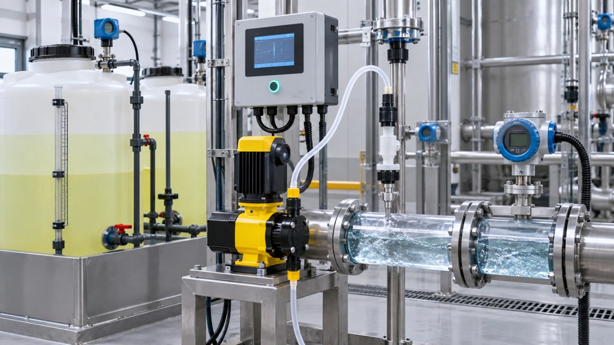
It stops dosing when the process is not in a valid state
Interlocks are often the simplest and most valuable protection against gross overfeeding. A dosing pump can be allowed to run only when a main circulation pump is operating, a flow switch confirms movement, a batch is active, or a permissive valve is open.
Consider a chemical injected into a recirculating pipe. If the circulation pump trips, continuing the chemical dose can create a concentrated pocket in the pipework or tank. An interlock stops the chemical pump immediately or holds it in a defined safe state. In a batch process, the same logic can prevent chemical addition outside the intended mixing or reaction stage.
Low-level protection at the chemical tank serves a different purpose but belongs in the same control strategy. It prevents dry running, loss of prime, and uncontrolled recovery behavior when a supply container is replaced. A low-level alarm alone is not always enough; the controller should have a defined response when chemical supply is unavailable.
It detects signals that should not be trusted
Not every abnormal value means the process suddenly needs more chemical. A broken cable, fouled probe, failed flow meter, empty sample chamber, or communication loss can all send misleading data. A capable control arrangement identifies out-of-range inputs, implausible changes, or lost signals and responds predictably.
The preferred response depends on the process. Some systems should stop chemical addition. Others may hold the last verified dose for a limited period, switch to a conservative backup rate, or require manual confirmation. Continuing automatic correction from an invalid measurement is usually the least defensible option because the controller can drive the pump toward maximum output without real process feedback.
Choose the control method based on what actually changes
A controller can prevent overfeeding only when its control basis reflects the source of changing demand. The table below is a practical starting point.
Combined control is often appropriate where process consistency matters. Flow pacing provides the base dose, while feedback makes smaller corrections. High and low process alarms, output limits, and no-flow shutdowns act as boundaries around the control loop. This approach avoids expecting one pH or residual signal to carry the entire control task.
Settings that can cause overfeeding even with automatic control
Installing a controller does not automatically produce stable dosing. Several setup errors can defeat its protective functions.
- Incorrect pump calibration: The controller may calculate the right command while the pump delivers more than assumed. Confirm actual delivery at the chemical concentration and backpressure used in service.
- Wrong signal scaling: A flow or analyzer input must be scaled correctly at both ends. If the controller interprets a moderate signal as a low-flow condition or a large process error, the resulting dose can be excessive.
- Controller action set in the wrong direction: For pH control, the pump must reduce the measured error in the intended direction. Reversed direct/reverse action can make the controller increase dosing as the process moves farther from target.
- Response settings that are too aggressive: Fast correction may appear responsive during commissioning but can become unstable once mixing delay and chemical reaction time are present.
- No minimum and maximum command boundaries: A controller should not be allowed to command a rate below a pump’s controllable range or above the process’s reasonable demand.
- Alarms without a pump response: An alarm that only appears on a screen may not prevent damage. Decide which alarm conditions should stop dosing, reduce it, or transfer the process to a controlled manual state.
A frequent misconception is that a narrow setpoint band always improves control. In a delayed chemical process, an overly narrow band can make the pump chase normal measurement noise. A stable process band, suitable filtering, and measured controller response are often more useful than constant small output changes.
Commissioning should prove the protective logic, not just the pump rotation
Before routine operation, test the complete dosing path under realistic but controlled conditions. Confirm that the pump stops when the relevant process flow stops. Check that a simulated high process value reduces or disables dosing where appropriate, and that a simulated low value cannot force output beyond the configured limit. Verify the response to probe failure, low chemical level, loss of flow signal, and power restoration.
Also inspect the physical side of the system. A controller cannot compensate for a leaking foot valve, gas-bound suction line, blocked injection quill, pulsation issue, poor chemical mixing, or an injection point located where process conditions are not representative. Mechanical faults can look like control problems because they cause the measured process value to lag, drift, or fail to respond as expected.
After adjustments, record the pump calibration, normal operating range, setpoints, alarm limits, interlock logic, and the reason for each setting. This makes troubleshooting much easier when a change in chemical strength, source-water condition, production rate, or equipment configuration affects dosing behavior.
When manual control is still appropriate
Manual dosing is not automatically unsafe. It can be appropriate for a stable, supervised process with predictable demand, especially during maintenance, analyzer cleaning, or controlled startup. The risk rises when manual mode becomes the normal workaround for an unreliable sensor or poorly tuned automatic loop.
When manual mode is necessary, retain the same physical safeguards: a defined maximum pump rate, no-flow interlock, chemical tank protection, and clear verification of the resulting process condition. Manual mode should be a deliberate operating state, not an uncontrolled default after an alarm.
What to check before changing the controller settings
Start with the process rather than the controller menu. Identify what is being controlled, where the chemical is injected, how long it takes to mix and react, and which measurement best represents the final condition. Then verify the pump’s actual delivery and the validity of every input signal. Only after those basics are confirmed should response settings be adjusted.
For installations that combine flow metering, analyzers, metering pumps, valves, and PLC or supervisory controls, component compatibility matters as much as individual specifications. G-ISC’s intelligent flow metering and control focus is relevant here: the useful question is not simply whether each device can communicate, but whether the complete control chain provides reliable measurement, clear fail states, and maintainable operating logic.
A chemical dosing system becomes safer when its controller is treated as part of the process, not as a speed dial attached to a pump. Limit the possible dose, link it to real operating conditions, validate the measurement, and define what happens when the information is no longer trustworthy. Those decisions are what prevent automatic dosing from becoming automatic overfeeding.
Recommended News
 Oct 10, 2026How Flow Control Automation Improves Dosing Accuracy in Chemical ProcessingFlow control automation improves chemical dosing accuracy with real-time feedback, smarter control logic, safer operation, and reliable lifecycle performance.● Elena Hydro
 Oct 18, 2026What causes a dosing pump controller to lose calibration?Dosing pump controller calibration issues explained: identify sensor drift, wiring faults, parameter errors, pump wear, and flow restrictions with practical troubleshooting steps.● Elena Hydro
 Oct 17, 2026How a chemical dosing pump controller prevents overfeedingChemical dosing pump controller safeguards prevent overfeeding with flow pacing, feedback, interlocks, and output limits. Learn smarter, safer dosing control.● Elena Hydro
 Sep 14, 2026How Food Processors Can Evaluate Dosing Controller Manufacturers for Hygienic AccuracyDosing controller manufacturer food processing guide: evaluate hygienic design, delivered-dose accuracy, CIP cleanability, allergen controls, alarms, and validation evidence.● Elena Hydro
 Aug 08, 2026How to Evaluate a Dosing Controller Manufacturer for Chemical Processing ProjectsDosing controller manufacturer chemical processing buyers trust should deliver accuracy, safe integration, and reliable support. Learn how to compare suppliers and reduce project risk.● Elena Hydro
 Jul 30, 2026Batch Controller Cost Breakdown: What Affects Price and Total Ownership?Batch controller cost depends on more than unit price. Discover what drives total ownership, from meter compatibility and integration to compliance, maintenance, and downtime risk.● Elena Hydro
 Jul 05, 2026Proportional Valve Hysteresis in Europe: Test Methods, Compliance, and Selection FactorsProportional valve hysteresis Europe explained: compare test methods, compliance expectations, and selection factors to choose stable, efficient valves with confidence.● Elena Hydro
 Jul 03, 2026Liquid Dosing System Manufacturer Checklist: 7 Questions Before You Request a QuoteLiquid dosing system manufacturer checklist: discover 7 key questions to compare accuracy, compliance, support, and total cost before requesting a quote.● Elena Hydro
 Jul 02, 2026Mass Flow Controllers Supplier Checklist: How to Compare Accuracy, Lead Time, and SupportMass Flow Controllers supplier checklist: compare accuracy specs, real lead times, and after-sales support to reduce downtime, control total cost, and choose with confidence.● Elena Hydro
 Jun 26, 2026Technical Comparison of Coriolis vs Magnetic Flow Meters for Accurate DosingTechnical Comparison of Coriolis vs Magnetic Flow Meters for accurate dosing—learn which option delivers better precision, reliability, and lower lifecycle risk.● Elena Hydro
 Jun 18, 2026Liquid Dosing System Factory Selection: Key Accuracy, Flow Rate, and Control FactorsLiquid dosing system factory selection starts with accuracy, flow stability, and control performance. Learn how to compare suppliers for reliable output, lower waste, and long-term process confidence.● Elena Hydro
 Jun 08, 2026Liquid Dosing System Factory Selection Guide: Accuracy, Flow Rate, and Control OptionsLiquid dosing system factory selection starts with proven accuracy, stable flow rate, and smart control options. Compare key criteria to reduce risk and choose a reliable supplier.● Elena Hydro
 May 23, 2026Flow Control issues that quietly raise energy and maintenance costsFlow Control issues can silently increase energy use and maintenance costs. Learn the warning signs, root causes, and smart evaluation steps to improve reliability and reduce lifecycle risk.● Elena Hydro
 May 22, 2026Flow control mistakes that quietly raise energy useFlow Control mistakes can quietly increase energy use, raise wear, and destabilize processes. Learn the hidden causes, key risks, and smarter ways to improve industrial efficiency.● Elena Hydro
 May 21, 2026Flow Control problems often start with one wrong assumptionFlow Control problems often start with one wrong assumption. Discover how to spot hidden risks, improve reliability, and make smarter industrial design and sourcing decisions.● Elena Hydro
 May 20, 2026Flow Control mistakes that lead to unstable outputFlow Control mistakes can trigger unstable output, higher downtime, and compliance risk. Learn the key errors, warning signs, and smarter selection strategies to improve reliability.● Elena Hydro
 May 19, 2026How to judge flow control stability before buyingFlow Control stability starts with real-world testing. Learn how to compare pressure response, repeatability, and lifecycle performance before buying with confidence.● Elena Hydro
 May 18, 2026Common flow control mistakes that raise system riskFlow Control mistakes in sizing, installation, and maintenance can quietly raise downtime and safety risk. Learn the hidden errors that impact reliability and sourcing decisions.● Elena Hydro
 May 17, 2026What to Check Before Upgrading a Flow Control SystemFlow Control upgrade guide: learn what to check before changing a system, from media compatibility and pressure limits to integration, compliance, and long-term reliability.● Elena Hydro
 May 16, 2026Flow Control issues that quietly increase operating costsFlow Control issues often raise operating costs long before failure occurs. Discover how pressure drift, leakage, oversizing, and poor response silently drain energy, uptime, and profit.● Elena Hydro
 May 15, 2026Flow Control Settings That Look Stable but Waste OutputFlow Control settings may look stable yet quietly cut throughput and raise energy use. Learn how to spot hidden output loss, judge settings by scenario, and improve capacity without sacrificing reliability.● Elena Hydro
 May 14, 2026Flow Control Problems That Raise Energy Use Without WarningFlow Control problems can quietly drive up energy costs, reduce reliability, and strain equipment. Discover the hidden warning signs, key system risks, and practical fixes before losses grow.● Elena Hydro
 May 13, 2026Flow Control problems that quietly raise energy costsFlow Control issues can quietly drive up energy costs through pressure swings, oversizing, drift, and poor tuning. Learn where waste hides and how to cut it before reliability and budgets suffer.● Elena Hydro
 May 12, 2026Flow Control Problems That Look Small but Hurt OutputFlow Control issues that seem minor can quietly cut output, raise scrap, and increase downtime. Learn the warning signs and practical fixes that restore stability fast.● Elena Hydro